.png)
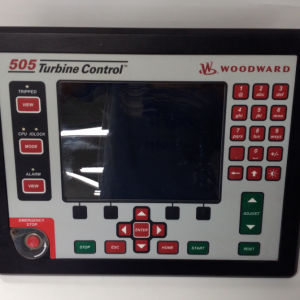
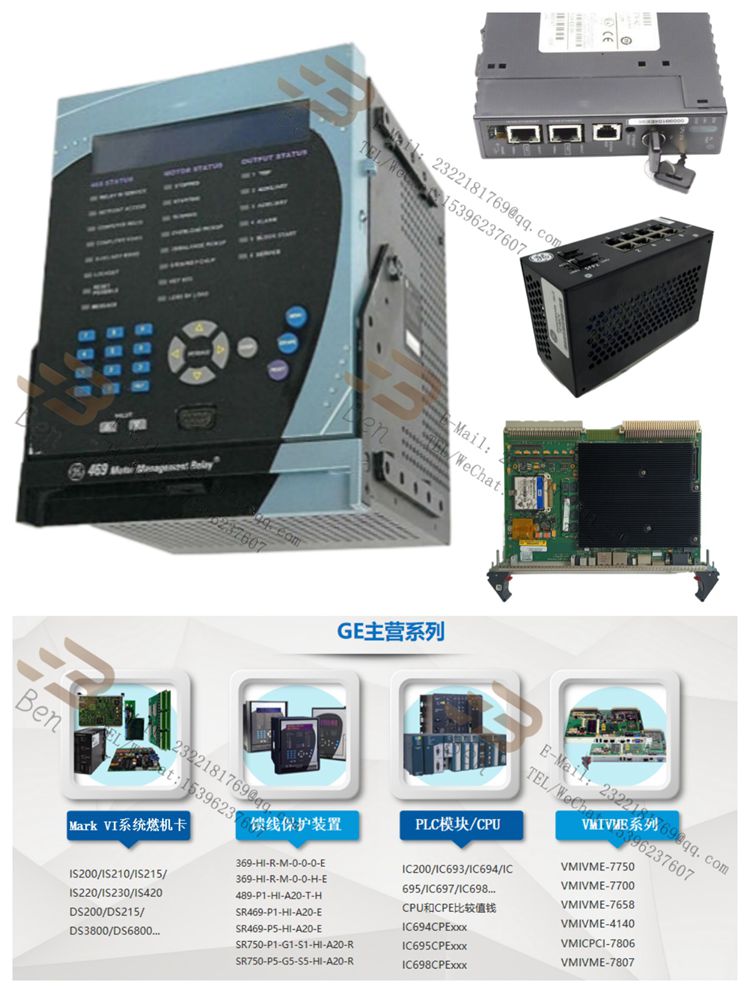
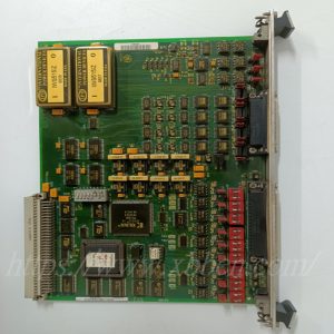
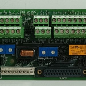
IS200TSVOH1BBB Exciter bridge interface board
The IS200TSVOH1BBB is a specific device from General Electric that is available primarily as part of the Speedtronic family of steam and gas turbine management systems. This device, known as exciter bridge interface Board, plays a key role in steam and gas turbine management systems by providing interface functions, voltage and current feedback, MOV fuse loss detection, and status indication, ensuring efficient, stable and safe operation of the system.
Its main functions include:
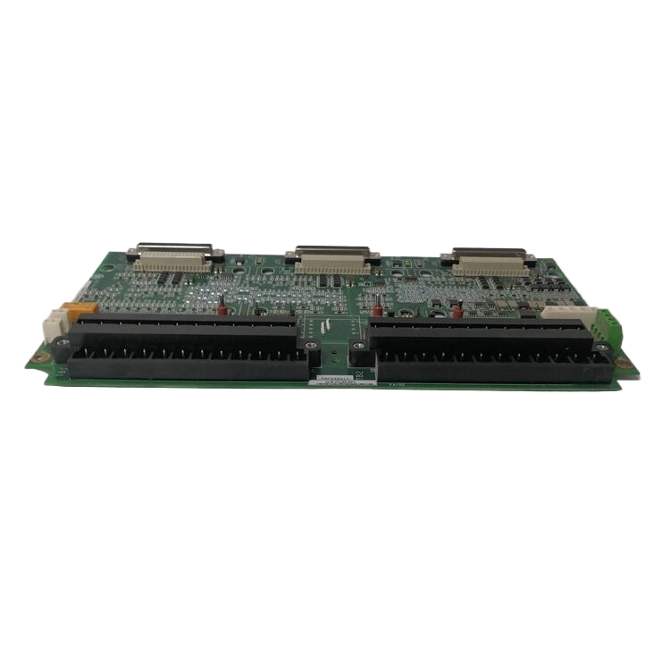
Interface features Provided: It provides most of the interface features between the EXIC exciter control interface board and the exciter bridge of the innovative series of medium voltage SP drivers. This enables communication and data exchange between different components.
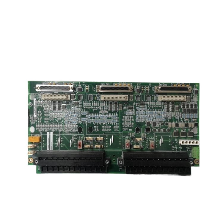
Voltage and current feedback: The board has multiple plug-in connectors that can be connected to discrete wired AC and DC inputs to create voltage feedback. The current feedback runs to the board through a specific connector, generated by a DC current shunt connected to the DC output terminal of the excitation bridge.
MOV Loss of Fuse detection: The board also provides MOV (metal oxide varistor) loss of fuse detection. The MOV is located in the SCR (thyristor rectifier) bridge and its signal is sent to the board via a vertical spike connector.
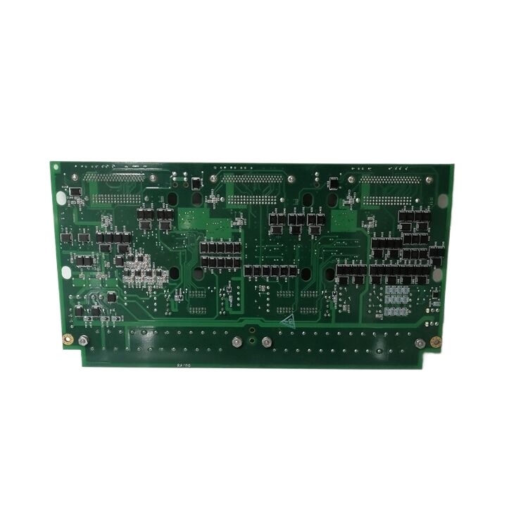
Status indication: There are nine leds on the board to visually indicate SCR gate pulse, power and isolation power status, and MOV fuse loss. This allows users to easily monitor the working status of the device.
Test points: To facilitate diagnosis and troubleshooting, the board provides 35 test points for signal access to connector J1 I/O signals and another 12 for access to power signals.
Reviews
There are no reviews yet.