The excitation controller is used to control the excitation voltage of the excitation winding on the generator, so as to obtain the smooth shape of the output voltage of the generation. A controller made of a voltage regulator, etc.
The working principle of excitation controller
Composition and function of the main loop
The main circuit of the device completes the two functions of rectification and demagnetization. The system adopts three-phase fully controlled bridge thyristor rectifier circuit to provide DC excitation current to the rotor winding of synchronous motor. The degaussing circuit is composed of thyristor 7, 8KGZ and diode GZ in inverse parallel, and actually consists of a high-power electronic switch, which completes the serial starting resistance of synchronous motor in the process of asynchronous starting, and automatically cuts it out after the end of starting, so as to ensure that the rotor excitation winding is neither open nor short circuit during the asynchronous starting of synchronous motor. So as to avoid the field winding under overvoltage and overcurrent.
The shaft end of brushless excitation generator is an alternator, whose rotor is the generating winding. The current sent out leads the silicon rectifier tube fixed on the shaft through the wire fixed on the generator shaft, and the DC after rectification directly enters the rotor winding. There is no rectifier brush in it, so it is called brushless excitation. Once popular for a period of time, but because the rectifier tube is broken, it has to stop, so it has been used very little, the basic use of self-compound system.
Typical brushless generator consists of five parts: ① main generator; ② AC exciter; (3) rotary rectifier device; (4) Automatic voltage regulator; ⑤ Permanent magnet auxiliary exciter (selected components).
In general small and medium-sized brushless synchronous generator, the secondary exciter is mostly omitted. The auxiliary winding or the main winding tap in the stator of the main engine provides the excitation power of the AC exciter instead of the auxiliary excitation.
In the three-phase brushless synchronous generator, AC exciter types include rotary mature synchronous generator, asynchronous generator and rotary phase compound transformer, but the rotary mature three-phase synchronous generator type AC exciter is the most widely used. The utilization coefficient of three-phase exciter is higher, which is conducive to reducing the volume.
The disadvantage of the brushless generator is that the electromagnetic inertia of the excitation system is large, so the dynamic characteristics are relatively poor. In order to improve the dynamic characteristics, the measures adopted are AC exciter using intermediate frequency frequency, due to the generator size and required excitation power constraints, most Marine brushless generator exciter frequency in 100 ~ 150 Hz. In addition, the brushless generator has higher requirements for the manufacture and installation of rotary rectifier.
Brushless excitation feature
- 1:Brushless excitation does not touch parts carbon brush and slip ring, simple maintenance, high reliability, long-term continuous operation and achieve less maintenance or maintenance free.
- 2:Because there is no rotating contact of conductive parts, there will be no spark, suitable for flammable gas and dust and other harsh environmental conditions of the operation.
- 3:The excitation power is small, and the reliability design of AVR is easy to implement.
- 4:For the main engine, it belongs to the separately excited synchronous generator, which is easy to run in parallel.
- 5:Compared with brush generator, it has larger volume and more effective material consumption
ABB’s IGCT is a new type of power semiconductor device for use in large power electronics suites
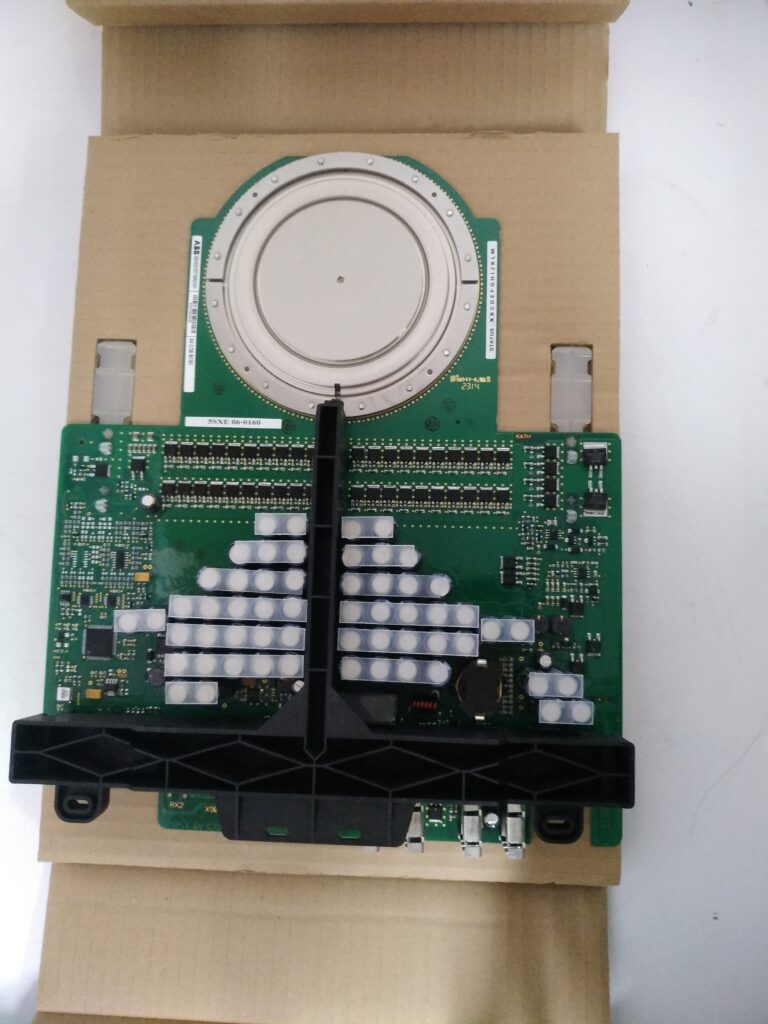
IGCT integrated Gate Commutated Thyristors (Intergrated Gate Commutated Thyristors) is a new type of power semiconductor switching device from medium-voltage converter to commutated thyristors (integrated gate commutator thyristors = gate commutator thyristors + gate unit).
IGCT has made great progress in power, reliability, switching speed, efficiency, cost, weight and volume of converter device, bringing a new leap to power electronic complete sets of devices. IGCT integrates the GTO chip with the reverse parallel diode and gate drive circuit, and then connects it with the gate driver at the periphery in a low inductance way. It combines the stable turn-off ability of the transistor and the advantages of the low-pass state loss of the thyristor, and gives play to the performance of the thyristor at the turn-off stage and presents the characteristics of the transistor at the turn-off stage. IGCT has the characteristics of large current, high blocking voltage, high switching frequency, high reliability, compact structure, low on-off loss and so on. It also has the advantages of low cost, high yield and good application prospect. It has been used in power system power grid device (100MVA) and medium power industrial drive device (5MW)IGCT in the field of medium voltage inverter successfully applied for 11 years (up to 2009), because of the high speed switching capacity of IGCT without buffer circuit, the number of power components required is less, and the reliability of operation is greatly increased.
The IGCT combines the high-speed switching characteristics of the IGBT (insulated gate bipolar transistor) with the high blocking voltage and low on-off loss characteristics of the GTO (gate off gate gate). Generally, the trigger signal is transmitted to the IGCT unit through the optical fiber. In the phase module of the ACS6000 marginal rectifier unit, each phase module consists of an IGCT, a diode and a clamp capacitor, and is powered by an independent gate power supply unit GUSP.